During my recent presentation, I showed how the 1/12–wavelength matching technique using a short length of 50- and 75-ohm coax could be used to get a 1:1 match to 50 ohms at the transmitter end of a 75-ohm dipole. This is what is usually called 1:1 SWR.
Rich KE1B pointed out that one could just use 75-ohm coax for the entire feedline, resulting in a 1.5:1 SWR, which can be dealt with by any common solid state amplifier. The SWR on the line is 1:1 so there is no additional loss due to line SWR.
My response was that this was a good comment (and I still think that it was) so using 1/12 wave matching in this case would not be worth the effort.
On rethinking the matter later, I realized that I should have given the response that I suggested for all antenna myths:
“Maybe, it depends, it is more complicated than that.”
Rich was “right on” if the dipole is cut for the center of the band, for example 7.15 MHz, and the user is not going to operate at other frequencies in the band. At 7.0 or 7.3 MHz using a 75-ohm line of about 1/2 wavelength at 7.15 MHz will give an SWR of about 2:1 at the band edges.
2:1 is about the limit for many solid-state amplifiers; beyond that the power is automatically reduced.
If the 1/12–wavelength match is used, as presented in the talk, then the SWR is 1:1 at the center of the band and only about 1.5:1 at the ends – so your solid-state amplifier will be happy and this will result in a 40-meter dipole that truly does not require a tuner.
To refresh your memory, the system suggested looks like this:
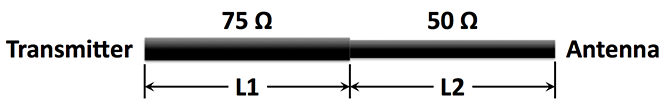
L1 and L2 are about 1/12 wavelength at 7.15 MHz, taking into account the velocity factor of the lines.
Musing about this made me think that it would be nice if other impedances for the two lines could be used to advantage. Playing with SimSmith and doing some trial-and-error, I quickly realized that it would be much nicer to have a program that would automatically calculate the best lengths L1 and L2, given the characteristic impedances for the two lines and a range of antenna impedances for the entire band of interest, not just the center. The program would print L1 and L2 such that the maximum SWR over the desired range of frequencies would be the minimum possible.
Because it is usually desirable to have a feedline that is not too short (10 feet would not work for an antenna that is 35 feet up) or too long for convenience and loss, the user can specify a min and max for the total feedline length.
The data input to the program, in addition to the parameters for the two lines, is a CSV (comma-separated values) file with the frequency and complex impedance (R+jX) at the antenna for each frequency. Such a file can be easily generated using the MMANA-GAL antenna modeling program, or, better, by measuring the values at the antenna in it’s final height above ground. This can be done with an antenna analyzer—easy with an AIM-4170C and somewhat more work with a cheaper analyzer. It is not necessary to have very many data points; on 40 meters I use about 10 and even that is more than is needed.
I wrote such a program, and using it in conjunction with SimSmith and having a lot of fun I came to some conclusions:
- Using only a 75-ohm line the SWR at the band edges would be about 2:1, as mentioned above. However, this is with a 1/2–wavelength transmission line. That might not be a convenient length (about 60 feet for the 40-meter dipole), and if a more convenient length is used the SWR at the band edges might be worse. For example, if the antenna is not high it might only require a 40-foot line, with a resulting SWR of about 2.3:1 at one band edge—more than we would like for a “no-tuner” line.
- It turns out that using a single 50-ohm line is a slightly better choice because it maintains a max SWR at the band edges of only about 2:1 for a range of lengths of 40 feet to 150 feet. The loss in the line, using LMR400 of 50 or 75 ohms, is only about 0.2 db. Note that RG58 has a loss of about 0.6 db under these conditions, but it is lighter and cheaper. The antenna Z varies quite a bit with antenna height. The 1/12–wave matching technique may give better results compared to a single line with some antenna heights. However, if the height results in a Z of around 50 ohm the user may not want to do anything special; just use 50-ohm coax.
- 86 feet of LMR-400 has a max SWR of only about 1.5:1 over the entire 40-meter band, so that would be an excellent choice. The loss would still be only 0.3 db; not bad.
- My spare 40-meter antenna is fed with 1/2 wavelength of window line (Z about 400 ohms). The Z of the antenna at the transmitter end is about 75 ohm at 7.15 MHz, as expected, but at the band edges it rises to about 2.8:1. This is not a surprise; the bandwidth of a 1/2–wave line will be smaller as the Z of the line differs more than the Z at the antenna compared to using a 75-ohm line. As I am using a good automatic “antenna tuner,” I probably won’t do anything to make the situation better.
- The idea of using two transmission lines with different impedances is more valuable on the 75-meter band where the bandwidth as a percent of the frequency is higher than for most other bands. An ordinary dipole fed with 50- or 75-ohm coax may have an SWR at the band edges of 6:1, while the 2-line technique results in a max SWR of < 2.4:1 with the optimum lengths calculated using my program. While this not a “no tuner” antenna system, it is within the reach of many transceivers with built-in tuners that often have a max SWR limit of 3:1.
- Using a 4-wire open-wire line with Z = 180 ohms, as described in the talk, in conjunction with a 500-ohm open-wire line (both lines easy and cheap to build), the best SWR at the band edges is 1.87:1 on 40 meters—not worth the effort compared to using a single LMR-400 75-ohm line of 86 feet—unless one is on a severe budget, and even then the cost of the wire will be a factor.
- MAJOR CONCLUSION: determining the worth of some antenna and feedline at only one frequency in the band of interest may lead to rather misleading results. It is much better to consider SWR, loss, and other parameters of interest over the entire range of frequencies for the band of interest.
If anyone is interested in my program I’ll be happy to supply it along with instructions on how to use it. It is not yet good enough in terms of documentation and robustness to be released as anything other than alpha code; but I have used it a lot and find it very useful, particularly for multi-band antennas such as a fan dipole.
Glen, KG0T